WR’ANGLE Barrier Tait Furlong · QUT Industrial Design
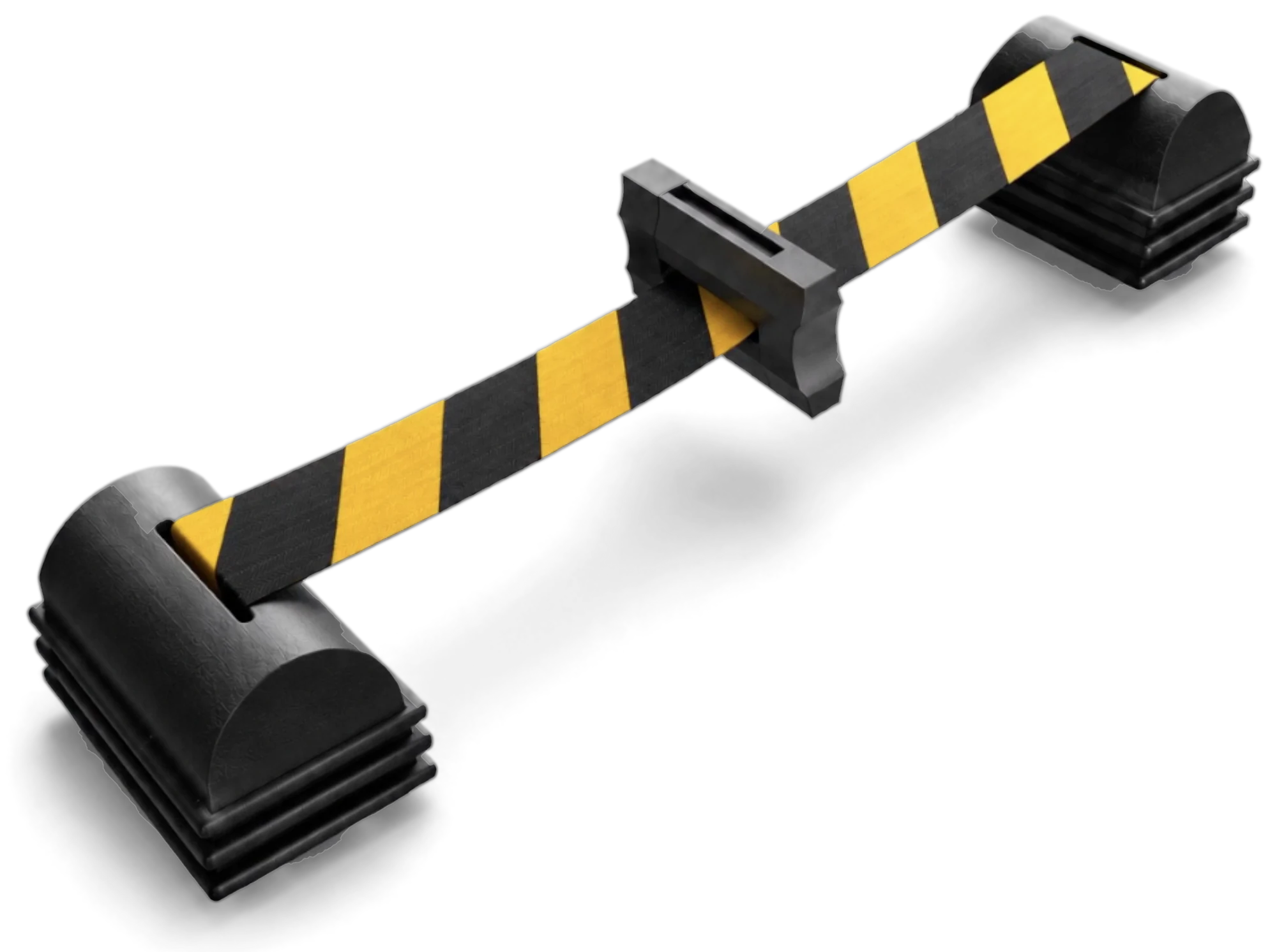
The WR’ANGLE Barrier: two black ribbed bases, joined by black-and-yellow hazard webbing that passes through the pivot.
Spring reel
Pivot
Webbing exit
Magnetic base
DNB311 Capstone · 2026

A three-point retractable barrier for aisles where forklifts and the public share the floor.

WR for wide reach. ANGLE for angled coverage.

Scroll

The problem

Most people near the forklifts were never briefed.

In a trade warehouse open to the public, the people at risk are mostly customers. They can't be trained, rostered or kitted out. In my observation log, 41 of 55 entries named a member of the public as part of the risk.

What staff actually use
“We mostly use the small retractable ones just because they're easier to move.”

Staff pick the barrier that costs them the least effort, even when it's the less visible one. Anything new has to be at least as easy to put out as the barrier it replaces.

The pivot

A third anchor turns a line into an angle.

The pivot holds the ends of both belts at one point. With both bases on one upright and the pivot on the other, the webbing crosses the aisle twice, at two heights. Customers read a clearly set barrier correctly and walked around an ambiguous one.

Two reels

Each base carries its own reel.

A prewound spring reel in each base pays out up to 3.5 m of 38 mm hazard webbing, so either belt can cross a wide aisle on its own.

Mounting

Magnets, not fixings.

Eight N42 disc magnets set into the backplates hold the bases to steel racking without tools. On open floor, the ribbed base sits flat.

In the aisle

Every Aisle, Every Angle.

Both bases go on one upright, one high and one low. The pivot goes on the opposite upright. The belts cross the aisle as a wide V.
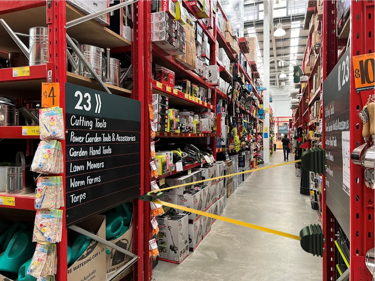
A hardware store aisle between red racking. Two barrier bases are fixed to the right-hand upright, one at about waist height and one near the floor. Two yellow belts run from them to the pivot on the left-hand upright.
1 · Pivot
2 · Upper base
3 · Lower base
  1. 1
    PivotHolds both belt ends on the far upright.
  2. 2
    Upper baseBelt crosses at an adult's eye line as they turn into the aisle.
  3. 3
    Lower baseBelt crosses near the floor, where a child or a trolley comes through.

A single belt reads as a line someone can duck under. Two belts set at an angle read as a closed opening from the main aisle.

Visualisation: barrier render composited into a photo from the observation site.
The parts

Every part, on the bench.

Eight views of the current build, from the full assembly down to the plate that holds the magnets. Specs come from my bill of materials. Production figures are estimates for a 1,000-unit run.

Plate 01 · Assembly

Two bases, two reels, one pivot

Every part in the unit, coming together. Two printed bases, two spring reels on stainless axles, a pivot in two halves, two backplates and eight magnets.
Prototype
≈ A$180 per unit, FDM PETG
Production
≈ A$88 per unit at 1,000, incl. tooling
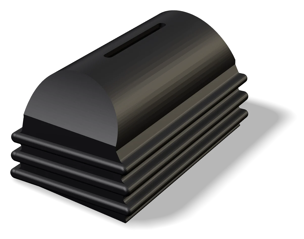
Render of a single base: a rounded hump with a webbing slot, over three ribs.
Plate 02 · Base

The base

A rounded hump over the reel, with the webbing slot along its crown. The ribs give a hand something to grip.
Qty
2
Material
PETG → PC-ABS
Process
Injection moulded, side action for slot
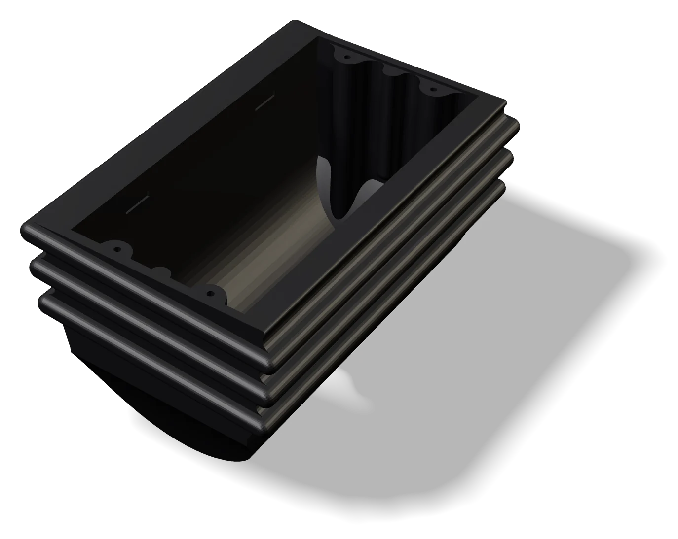
Render of the base turned upside down, showing the hollow cavity and the cradles the reel sits in.
Plate 03 · Inside the base

Where the reel sits

The reel drops into moulded cradles and the backplate screws over it. A retraction brake isn't in this build yet.
Reel
POM (acetal)
Spring
Prewound, 301 stainless
Axle
Ø4 × 115 mm, 304 stainless
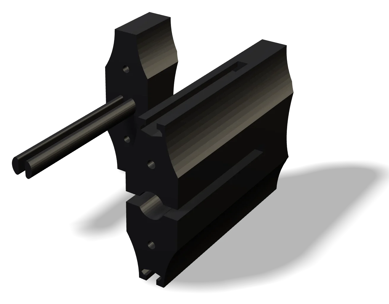
Render of the two halves of the pivot separated, with an alignment pin between them.
Plate 04 · Pivot

The pivot

Two halves close over the webbing and bolt together. The concave flanks let it nest between the two bases for stand-by, in a 100 × 160 × 126 mm block.
Qty
1 (2 halves)
Fixing
M4 socket head + nut × 2
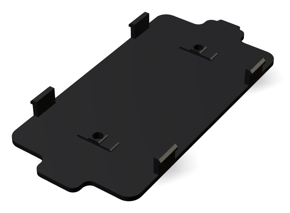
Render of the flat backplate with locating tabs and two screw points.
Plate 05 · Backplate

The backplate

Closes the base and carries the magnets. Tabs locate it before the screws go in.
Magnets
N42 disc, Ø20 × 5 mm, × 8
Pull
≈ 6.1 kg each
Fixing
M3 × 10, 4 per base
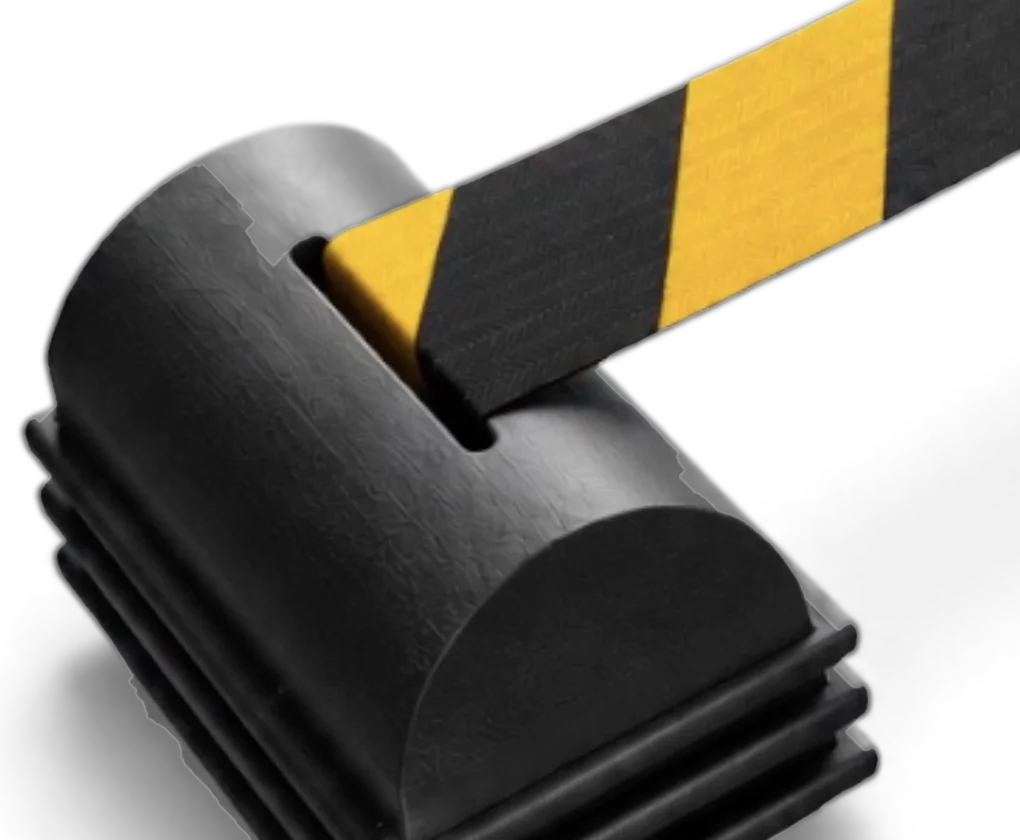
Close-up render of the webbing leaving the slot on top of a base.
Plate 06 · Detail

The webbing exit

The belt leaves from the crown, so it pays out level with the top of the base.
Webbing
38 × 0.8 mm polyester
Length
3.5 m per reel
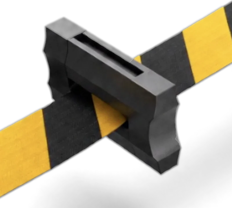
Close-up render of the hazard webbing passing through the pivot.
Plate 07 · Detail

Webbing through the pivot

The belts run through the pivot body rather than hooking onto it, so the pivot stays on the webbing when the barrier goes slack.

Front elevation looking down the aisle. Both bases sit on the right-hand upright, one high and one low. The pivot sits on the left-hand upright at middle height. Two belts run from the pivot to the bases, forming a V on its side, in front of an adult and a child. Pivot Base Base Aisle width
Plate 08 · Elevation

Looking down the aisle

Front on, the barrier is a V on its side. Both bases share one upright and the pivot takes the other, so the opening is closed at an adult's height and a child's.

End-on schematic. The pivot is a tall bar with all four corners curved in. The two bases start nested under it, humps up, hugging its lower corners. They swing out to the sides like wings, turn over, and nest over the top of the pivot, humps down, then swing back. Pivot Base Base
Plate 09 · Orientation

Either side of the pivot

The pivot is a bar with all four corners curved in to the radius of the base humps. Both ends are the same, with a magnet in each end face, so the bases nest around either end: under it, humps up, or over it, humps down.

  1. Under the pivot
  2. Swung out
  3. Over the pivot
Schematic, viewed end-on, traced from the stand-by render.
On site

See it on the floor.

Two minutes on site with the prototype: set across an aisle, angled off the racking, picked up and put down, and packed into stand-by.

Wide reachAngled usePick-up, put-downStand-by